


You want information for
G3 Gauge
If you would like a quotation or have any questions about the product, please contact us:
- by email at info@saugnac-gauges.com
- by telephone on +33 9 62 07 18 68

Technical specifications
| |||
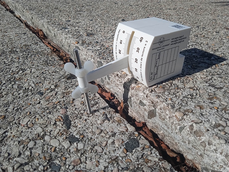
Overview of the G3 gauge for monitoring misalignment / offsetThe G3 gauge is designed to measure the evolution of a vertical misalignment (uneven floor slabs) or horizontal misalignment, or more generally, the evolution of movement perpendicular to an “X,Y” reference plane.  Monitoring the evolution of a horizontal misalignment: floor slab failure or ceiling sagging (A = structure whose movement is to be measured, B = fixed reference structure, d = misalignment)  Monitoring the evolution of a vertical misalignment: pillar leaning out of true or structure sliding (A = structure whose movement is to be measured, B = fixed reference structure, d = misalignment) The measurement is taken using a vernier reading to 1/10th of a mm, corresponding to 2/10th of a mm of movement.
A = B: Plane Z | |||
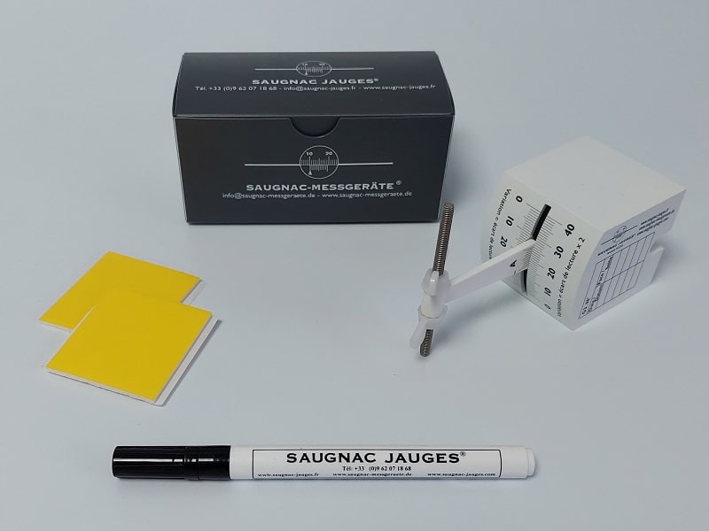
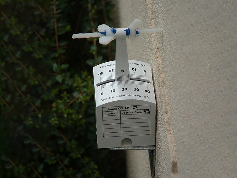
How to fix the G3 gauge?Its cube shape allows it to be used in any position: on a plinth, in vertical or horizontal angles, by choosing one of its 5 faces to fix the gauge (see below for examples of installations). Two fixing methods are possible:
A: 2 4/40 screws, B: Intermediate plate, C: Self-adhesive tab, D: E.J The sensor length is adapted to the size of the misalignment: an offset of up to approximately 50 mm is possible; beyond that, a special assembly is required, please contact us if needed. Examples of installations: G3 gauge installed on a ceiling with the supplied self-adhesive tabs G3 gauge installed with an intermediate plate on an uneven and damp surface G3 gauge fixed on its side to measure settling G3 gauges fixed to measure a pillar leaning out of true relative to its capital following an earthquake Adjusting the sensor length according to the misalignment Creating a special assembly for a large misalignment | |||
How to protect the G3 gauge?We offer protection with a thermoformed plastic cover or an IP65 aluminium cover. 1- Protection with the plastic cover
2- Protection with the aluminium cover
| |||
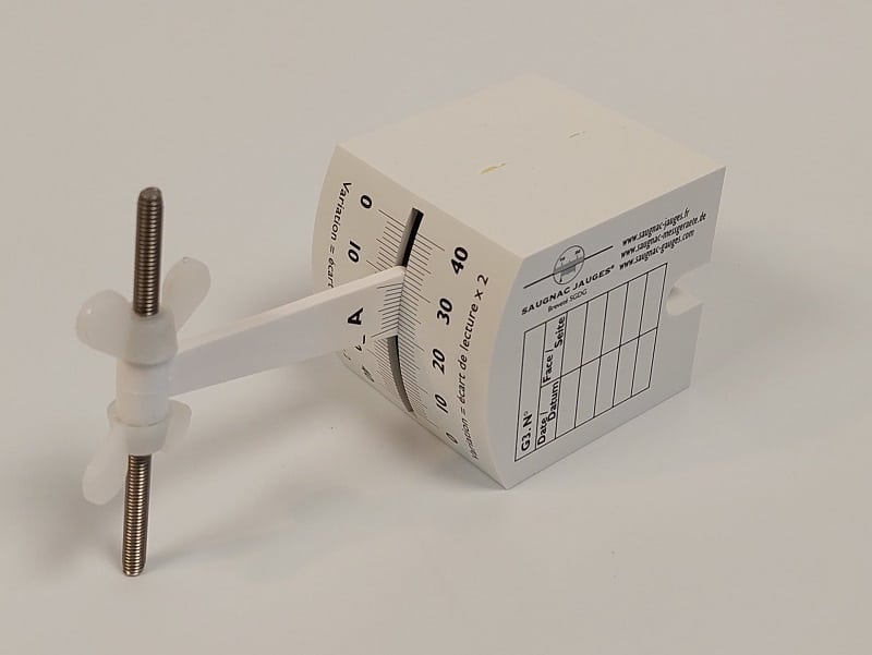
How to read the G3 gauge?The reading is taken using the vernier principle, to 1/10th of a mm. Note the letter of the face read, A or B, in order to compare measurements with the same face over time. a) Reading the mm:  The millimetre division of the graduation located to the left of the ꓕ indicates the measurement as a whole number of mm. In the example, the reading is therefore: 12 mm. b) Reading the decimal:  Look for a line on the vernier that coincides with a line on the measuring scale. This vernier line indicates the figure corresponding to the 1/10th of a mm. In the example, the reading is therefore: 4/10th of a mm So the measurement corresponds to 12.4 mm Due to the construction of the gauge, for geometric reasons, the evolution of the misalignment is equal to 2 times the difference between the 2 measurements taken. | |||
Recording kitWe offer an add-on recording kit to be mounted on the G3 gauge. This kit makes it possible to graphically record the maximum and minimum deformations of the structure. More information on the G3 recording kit product page. | |||
Download the Saugnac.app application to monitor your G3 gauge measurementsThe Saugnac web application, completely free with no limitations, is available on PC or smartphone at https://saugnac.app. Each G3 gauge has a unique QR code and ID to associate the measurements with the gauge. This application allows you to:
Find all the explanations on how the application works |

To install the G3 gauge if surface is irregular, damaged, damp or of poor quality. Delivered with impact anchors.

G3 Protective cover in IP65 aluminium. Fourni avec visserie. Delivered with impact anchors.

G3 Protective cover in thermoformed plastic. Fourni avec visserie. Delivered with impact anchors.

For graphic recording of structural yielding. To be mounted on the G3 Gauge. This new device records the maximum and minimum distortion on the graph.