G6 Gauge

141,20 w/o VAT per box 5 units

  • For cracks or deformation with movement on 2 axes: monitors changes in opening and shear displacement within a single plane
  • Resolution of 0.1 mm in translation and rotation (i.e. 0.1 mm horizontally and ~0.33 mm vertically)
  • Track and calculate X and Y axis measurements with the free Saugnac.app
  • Easy fixing with supplied self-adhesive tabs or mechanical fixing using the pre-drilled holes.
  • Supplied in a box of 5 gauges with a marker pen and detailed instructions.

Made in France Made in France

Technical specifications

  • Resolution
    0.1 mm in translation and rotation, i.e. 0.1 mm horizontally (X) and 0.33 mm vertically (Y)
  • Monitoring type
    2-axis crack monitoring
  • Crack type
    Crack in a single plane with movement on 2 axes, typically with uneven width
  • Usage
    Indoor / Outdoor: weather and UV resistant
  • Fixing
    Adhesive bonding with supplied self-adhesive tabs, or mechanical fixing with screws (sold separately)
  • Self-adhesive installation conditions
    Installation temperature: between -10°C and 35°C. Effective bonding from -40°C to +80°C
  • Dimensions
    200 mm x 95 mm x 3 mm
  • Measurement range
    approx. 20 mm (possible variation between maximum and minimum reading)
  • Weight
    20 g
  • Material
    Impact-resistant calendered PVC with UV stabiliser
  • Linear expansion coefficient
    7×10⁻⁵ m/m/°C

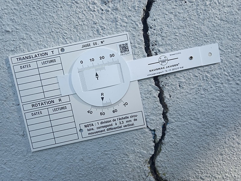
Presentation of the G6 gauge for 2-axis crack monitoring

The G6 gauge is designed to measure changes in the opening (gap) and shear displacement of crack edges, or any type of joint, within a single plane.
The combination of 2 verniers — for translation and rotation — allows the device to track deformation changes under different stress conditions.

G6 gauge diagram – axis of rotation A and crack B

A: Axis of rotation, B: Crack

Illustrative example of subsidence causing a crack with uneven width This device is recommended for studying cracks with uneven edges — wider at one end — typically caused by differential settlement or subsidence.

More generally, the G6 gauge is used to monitor any movement along 2 axes: an opening and a shear displacement between 2 structures. When used with an aluminium angle bar, it is also possible to monitor settlement and opening between two structures meeting at an angle (see installation examples below).

Each gauge has a unique QR code and identifier, enabling direct monitoring within the Saugnac application supplied with the product.

Illustrative example: subsidence of the subfloor.

How to install the G6 gauge

Two fixing methods are available for the G6 gauge:

  • By adhesive bonding: fixing is quick and easy using the supplied double-sided self-adhesive tabs. On smooth surfaces — partitions, interior walls, wallpaper or thin plaster — the self-adhesive tabs alone will be sufficient.
    If necessary, particularly if the surface is not completely flat or has irregularities, bonding can be reinforced with a fast-curing twin-syringe epoxy adhesive.
  • By mechanical fixing: for rough, damp or difficult surfaces, fix using large-head screws. The G6 gauge is pre-drilled with 3 holes of ø 4 mm, making mechanical fixing straightforward on any surface type.
    For difficult surfaces (crumbling, dusty, uneven or damp), mechanical fixing is recommended to prevent any risk of detachment. Bags of 50 screws and wall plugs are available, as well as a ready-to-use mechanical fixing kit including a 4 mm drill bit, a screwdriver and 40 plugs and screws.

Installation examples:

Mechanical fixing of the G6 gauge on a breeze-block wall
G6 gauge mechanically fixed to a breeze-block wall

G6 gauge fixed with supplied self-adhesive tabs on a crack with uneven width
G6 gauge fixed with self-adhesive tabs on a crack with uneven width

G6 gauge installed with an extension (using an intermediate plate)
G6 gauge installation with extension using an intermediate plate

Two G6 gauges positioned at right angles for monitoring vertical cracks

G6 gauge installed for monitoring oblique cracks

G6 gauge combined with a G3 gauge in a church to monitor both 2-axis deformation and misalignment
G6 gauge combined with a G3 gauge in a church to monitor 2-axis deformation and misalignment

G6 gauge installed at an angle using an aluminium angle bar

G6 gauges installed on a crack in the wall of the Ishtar Gate
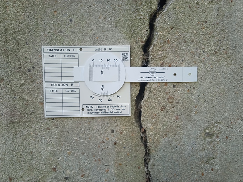
 

Installation tips

Ideally, the gauge should be fixed so that the arm is perpendicular to and straddles the crack.
To make movement interpretation easier, it is recommended to position:

  • The T vernier triangle between 10 and 11
  • The R vernier triangle between 50 and 51

This ensures that the sliding tongue arm is parallel to the long side of the gauge body.

G6 gauge correctly positioned with vernier T between 10-11 and vernier R between 50-51

Example of correct positioning with T vernier between 10 and 11, and R vernier between 50 and 51

Protection

The G6 gauge can be protected by a transparent PPMA sheet measuring 150 × 300 × 1.1 mm.
This protection is recommended when the gauge is installed in busy areas, schools or public places.

G6 gauge with protective PPMA cover fixed with impact anchors

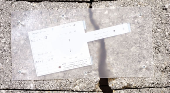
Fixing the G6 gauge and its protective cover with impact anchors

In locations with heavy footfall and a significant risk of damage, the removable E1 gauge with P2E1 plates for 2-axis monitoring may be used instead. After each reading, only the transparent plates remain on the surface, eliminating any risk of damage.

How to read the G6 gauge on 2 axes

For the T vernier (translation):

  • The upper scale is graduated in mm from 0 to 30: this is the main measurement scale.
  • The lower section with the T marker is mobile: this is the vernier scale to 1/10th of a mm (10 vernier divisions correspond to 9 mm on the main scale).

For the R vernier (rotation):

  • The lower scale is graduated in mm from 40 to 70: this is the main measurement scale.
  • The upper section with the R marker is mobile: this is the vernier scale to 1/10th of a mm (10 vernier divisions correspond to 9 mm on the main scale).

Reading the G6 gauge – example of 2-axis crack measurement

a) Reading the mm value:
For vernier T, the T marker sits between graduations 10 and 11 on the main scale: the reading is therefore 10 mm.
For vernier R, the R marker sits between graduations 49 and 50 on the main scale: the reading is therefore 49 mm.

b) Reading the decimal value:
Find the vernier line that aligns with a line on the main scale.
For vernier T, graduation 7 aligns with a line on the main scale: the decimal value is therefore 7/10th of a mm.
The T reading is therefore 10.7 mm.

For vernier R, graduation 9 aligns with a line on the main scale: the decimal value is therefore 9/10th of a mm.
The R reading is therefore 49.9 mm.

How to obtain X and Y axis values

To make rotation interpretation easier, X and Y values can be calculated using the following reference frame:

  • The origin corresponds to the centre of the disc
  • The X axis corresponds to the main axis of the sliding tongue in its initial position
  • The Y axis corresponds to the axis perpendicular to X passing through the centre of the disc

The diagram below shows an example where the gauge body is intentionally not aligned with the sliding arm, in order to clearly illustrate the reference frame principle.

X and Y axis reference frame for the G6 crack gauge

The initial position at installation defines the reference frame. For ease of interpretation, it is recommended to fix the gauge body parallel to the sliding tongue arm axis where possible (see installation tips above). This way, the X axis is parallel to the gauge body.

Example of the initial reference frame after a rotation movement:

G6 gauge – reference frame after rotation movement (illustrative, movement amplified)

Illustrative diagram – movement amplified for clarity

Calculating movement on the Y axis

The movement value along the Y axis corresponds approximately to the difference between two R vernier readings, multiplied by 3.3.

Example:

– Reading 1 of R = 49.9 mm

– Reading 2 of R = 49.4 mm

– Difference R2 − R1 = 49.4 − 49.9 = −0.5 mm

– Movement along Y axis = −0.5 × 3.3 = −1.65 mm

Calculating movement on the X axis

Movement along the X axis simply corresponds to the difference in the T vernier readings. Rotation causes a negligible variation in X: a change of 1/10th of a mm on the Y axis corresponds to a difference of 0.5 micrometres on the X axis (i.e. 0.0005 mm).

Download the Saugnac.app to track your measurements

Saugnac app – X and Y axis tracking for the G6 gauge G6 gauge tracking graph in the Saugnac application

The Saugnac web application is completely free with no limitations and is available on PC and smartphone at https://saugnac.app. It allows you to:

– identify each gauge and its readings using its unique QR code

– record readings and automatically calculate the X and Y axis variation for the G6 gauge based on T and R values

– retrieve temperature and humidity data via geolocation

– calculate readings with thermal expansion correction based on temperature

collaborate with multiple users on the same gauge

– manage alert thresholds

– organise gauges by location and view them on a map

export data in Excel format

– display automatic graphs

share data with other users without an account

– access the application from your PC or smartphone

– add readings offline without an internet connection

Find out more about the Saugnac application.

Related Products

  • colle pour fixer les témoins de fissures

    Glue

    17,50 w/o VAT

    Fast-curing epoxy adhesive in a twin-syringe for reinforced bonding in cases of significant surface roughness or high moisture

  • Mechanical Mounting Kit

    Mechanical Mounting Kit

    27,30 w/o VAT

    Mechanical fixing kit for surfaces unsuitable for self-adhesive installation (includes 1 drill bit + 1 PZ1/PZ2 screwdriver + 40 wall plugs and screws)

  • Bag of anchors and screws for Saugnac crack monitor

    Mechanical Fastening Pack

    15,00 w/o VAT per pack of 50 units

    Bag of 50 anchors and screws for mechanical fixing on surfaces unsuitable for self-adhesive mounting

  • corniere alu

    Aluminium angle bar

    9,90 w/o VAT

    For measuring the variation in a crack in a vertical or horizontal internal angle (with self-adhesive tabs and 1 impact anchor).


  • Protection de jauge G1 avec anti UV et 4 chevilles à frapper

    G6 high protection anti-UV

    9,50 w/o VAT

    Protection with anti-UV for G6 gauges fixed outside. Delivered with impact anchors.